A Simple Physics Project for my friend’s brother in an Engineering College

Wireless Electricity Transmission - Thumbnail
The concept of transferring electricity from one coil to another is not a new concept. It was demonstrated practically by Nikola Tesla in the early 1890. Nikola Tesla introduced electrodynamics induction or resonant inductive coupling by lighting up three light bulbs from the distance of 60 feet from the power source. Here as a Physics Project for one of my friend’s elder brother in an Engineering College have asked me to make a mini Tesla coil to transfer the energy. And, here is what I made for him and this simple project is appreciated by his dean – and I am happy for him.

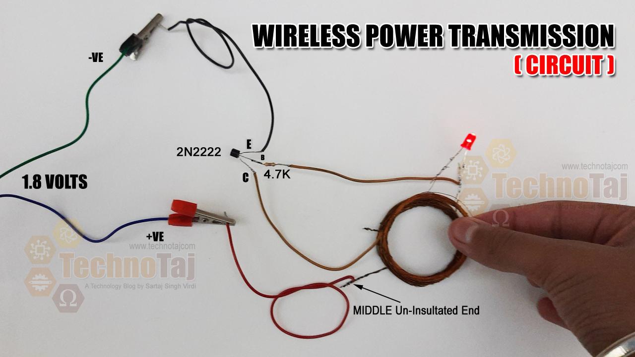
Wireless Power Transmission Circuit
Wireless Power Transfer (WPT) is a process of transferring power through air without using any wires or physical contact. In this wireless system, the Transmitter Section generates a time-varying or high-frequency electromagnetic field, which transmits power to the Receiver Section without any physical connection. The Receiver extracts the power from the magnetic field and supplies it to the load in this case it is Light Emitting Diode (LED). Therefore, to convert the electricity to an electromagnetic field, two coils are used as Transmitter Coil and Receiver Coil.
The transmitter coil is powered by alternating current and creates a magnetic field, which is further converted into a usable voltage across the receiver coil.
The Transmitter Circuit, consist of Coils that are connected across the collector of the transistor, 20 turn on the both sides. The Receiver circuit is built around three components – A 2N2222 Transistor, a 4.7K Ohm Resistor, and a Center Tapped Air Core copper coil made using insulated wire. The Receiver Circuit just has a Red Light Emitting Diode connected across the 40 turn insulated copper wire based coil.
WIRELESS POWER TRANSMISSION (WPT) CIRCUIT
In this circuit I am using a transistor 2N2222 and the heart of the circuit is the coil at transmitter end and receiver end. Care must be taken to make the coils. Please follow the pictures that I am sharing or visit my youtube channel to see how it is being built.
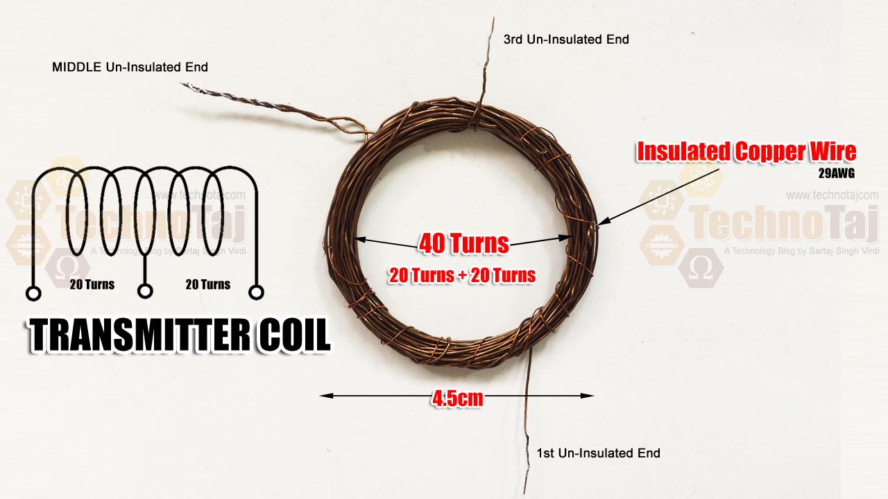
Transmitter Coil
For the coil you can use 29SWG insulated copper wire that you can extract from a defective transformer very easily. Center tapped coil formation is done on the transmitter and receiver circuits by winding it on a fevicol tube of 100gm. To be precise the coil diameter for the transmitter and the receiver coil should be 4.5cm dia.
For the transmitter circuit, just wind the insulated copper wire 20-turns, then the loop for center tap connection and again make 20 turns of the insulated wire coil. For the receiver circuit coil, just make 40 turns of coil winding without the center tap.
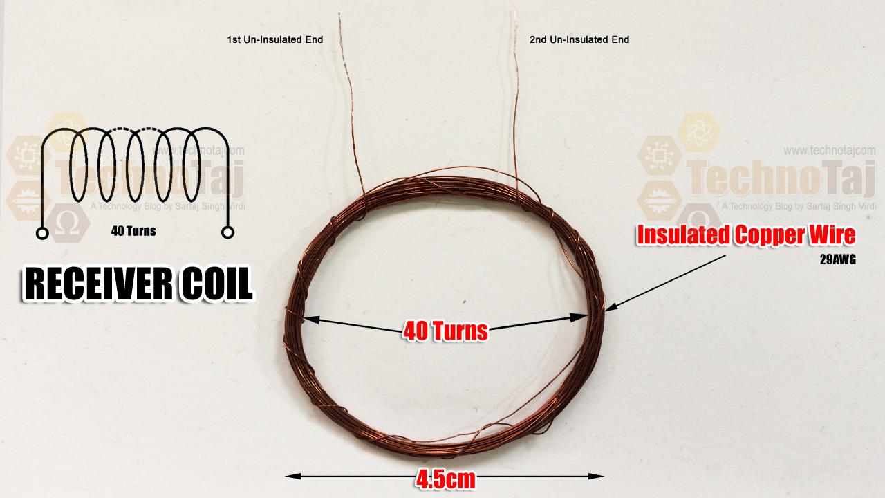
Receiver Coil
Please see the pictures to learn more about how to create the coils. It is the most crucial part of the project. A wrong coil would fail the entire project.
THE WORKING
Transmitter Circuits are constructed as shown in the picture and powered using a 1.5V battery (it can be powered by 1.8V too). The circuit can’t be used for more than 1.8 Volt power supply as transistor may heat up for excessive power dissipation. However, for more rating and higher voltages, additional driving circuits are needed.
This wireless electricity transmission is based on the Inductive coupling technique. The circuit consists of two parts-
TRANSMITTER CIRCUIT AND THE RECEIVER CIRCUIT PRINCIPLE
In transmitter section of the circuit, the Transistor (2N2222) is generating high-frequency AC current across the coil and the coil is generating a magnetic field around it. As the coil is center tapped, the two sides of the coil start to charge up. One side of the coil is connected to the resistor and another side is connected to the collector terminal of NPN transistor. During the charging condition, the base resistor starts to conduct which eventually turns on the transistor. The transistor then discharges the inductor as the emitter is connected with the ground. This charging and discharging of the inductor produces a very high frequency oscillation signal which is further transmitted as a magnetic field.
In the Receiver Circuit the Magnetic field is transferred into the other coil, and by the Faraday’s law of induction, the receiver coil start producing EMF (Electromagnetic Flux) voltage which is further used to light up the LED (Light Emitting Diode) for the project in hand.
Note:
The LED should light up when the Receiver Coil is brought within the distance of 7cm of the Transmitter Coil. As you near it to the transmitter coil, the LED should brighten up considerably. To improve the transmission distance, wind up the coil properly and increase the no. of turns in the coil.
APPLICATIONS
Wireless power transfer (WPT) is a widely discussed topic in the electronics industry. This technology is growing rapidly in the consumer electronics market for Smartphones and Contactless Chargers.
Major Benefit of Wireless Power Transmission Technology
A major benefit of wireless power transmission is that the product life can be increased by preventing the physical damages due to charger insertion across the connectors or the ports. Multiple devices can be charged from a single dock. Electronics vehicle can also be charged using wireless power transfer during the car is parked.
COMPONENTS REQUIRED
- Transistor 2N2222 x 1
- Resistor 4.7K x 1
- Insulated Copper Wire 10meters (approximately)
- Red LED x 1
- 1.5V Battery
COST : Rs.15
-
- Wireless Power Transmission Circuit
-

- Wireless Power Transmission Practical Connection
-
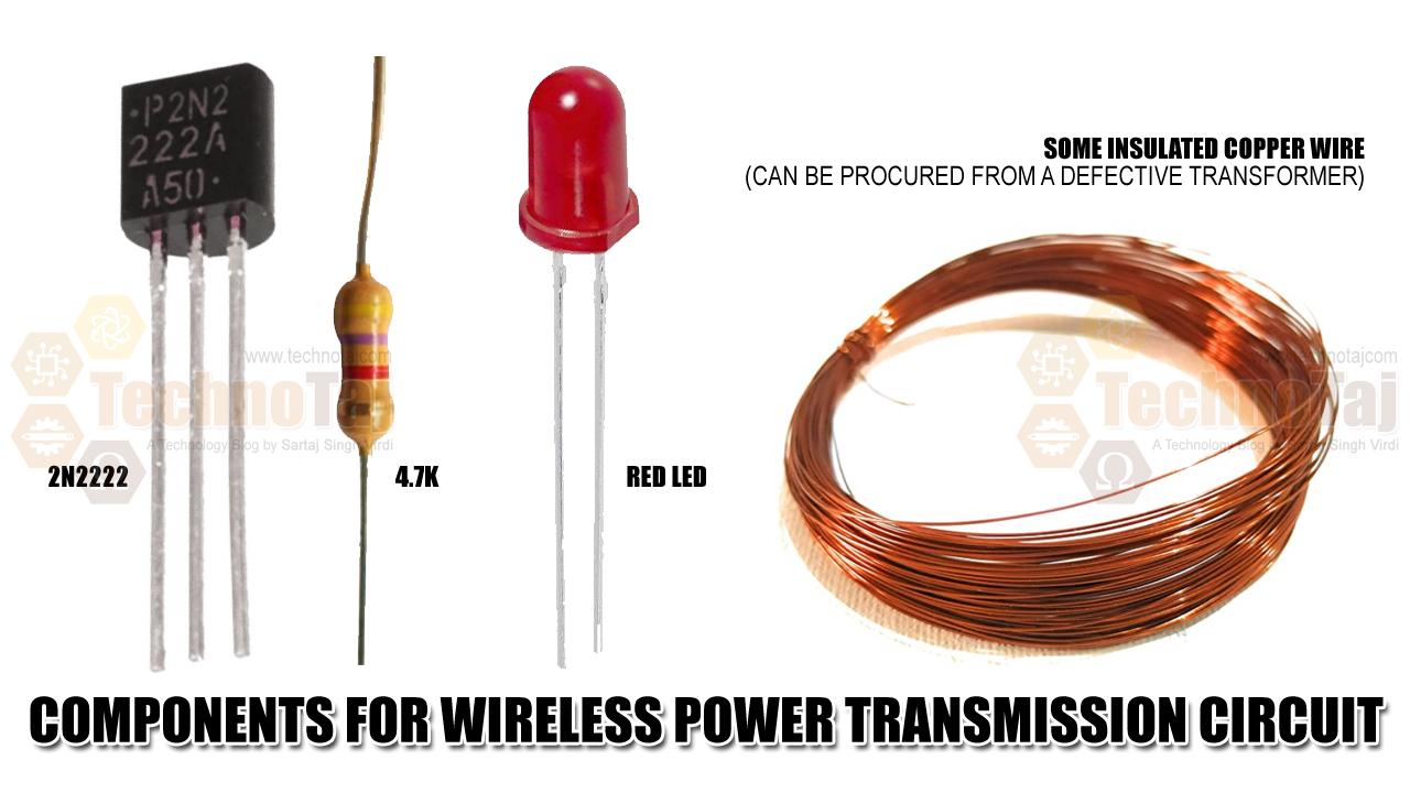
- Components for Wireless Power Transmission Circuit
-
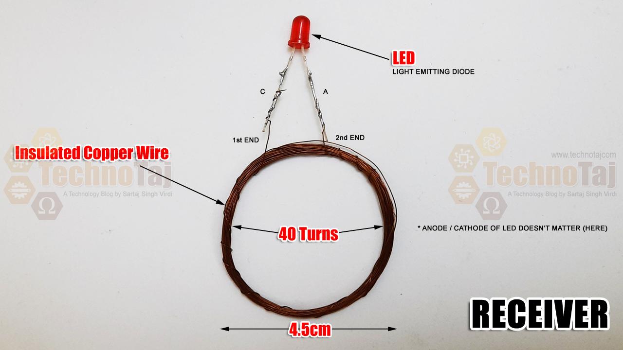
- LED Coil
-
- Receiver Coil
-
- Transmitter Coil
-

- Testing Wireless Electricity Transmission
-

- 7cm Away LED Begins to Glow
-

- Wireless Electricity Transmission
-
- Wireless Power Transmission
-

- Opening up a Damaged Transformer
-

- Bobbin with Insulated Copper Wire Coil Removed
Mohamad Fazly Effendy Bin Rosli