On the specific demands by some of my Facebook page visitors, I have redone this simple Latch Switch Circuit that can 'hold' the circuit in either ON or OFF state until any external signal is applied to it. The signal is supplied using ‘Push to On’ Buttons.
The concept of a Latch Circuit is that it retains its position (either ON or OFF) even after the input signal is removed and can store one bit of information as long as the device is powered. In the two circuits presented here NO Transistor or any other CMOS IC is used – so it is pretty simple and straight forward to assemble.
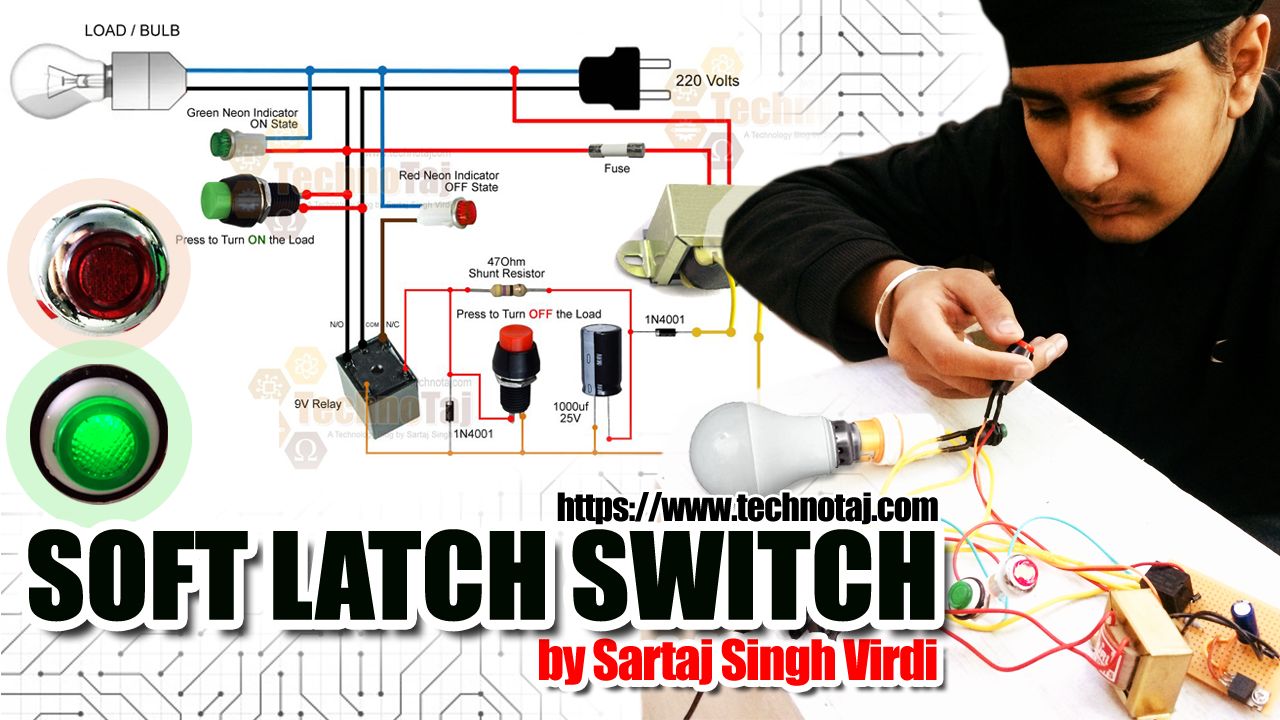
Soft Latch Switch by Sartaj Singh Virdi
USES OF A LATCH SWITCH
This Simple Latch Circuit can be used in various types of hobby gadgets, professional products, extension leads, sensitive electronic products and in lighting systems. The advantage of this latch switch is that it cuts of power to itself when in OFF state. Also, this Latch Switch Circuit comes with a facility to disconnect the load when power supply fails and resumes saving sensitive electronic products from any sudden surge when power comes back.
I am planning to use this Latch Switch in my mega project – ‘A complete Work-Bench’. I am already in process of making a very interactive workbench with various features and will be in a position to post it in next 2 months.
Soft Latch Circuit - 01
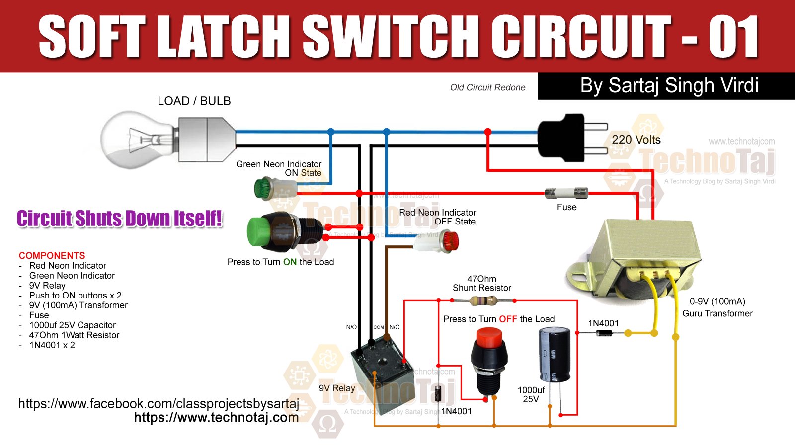
Latch Switch Circuit Number 1
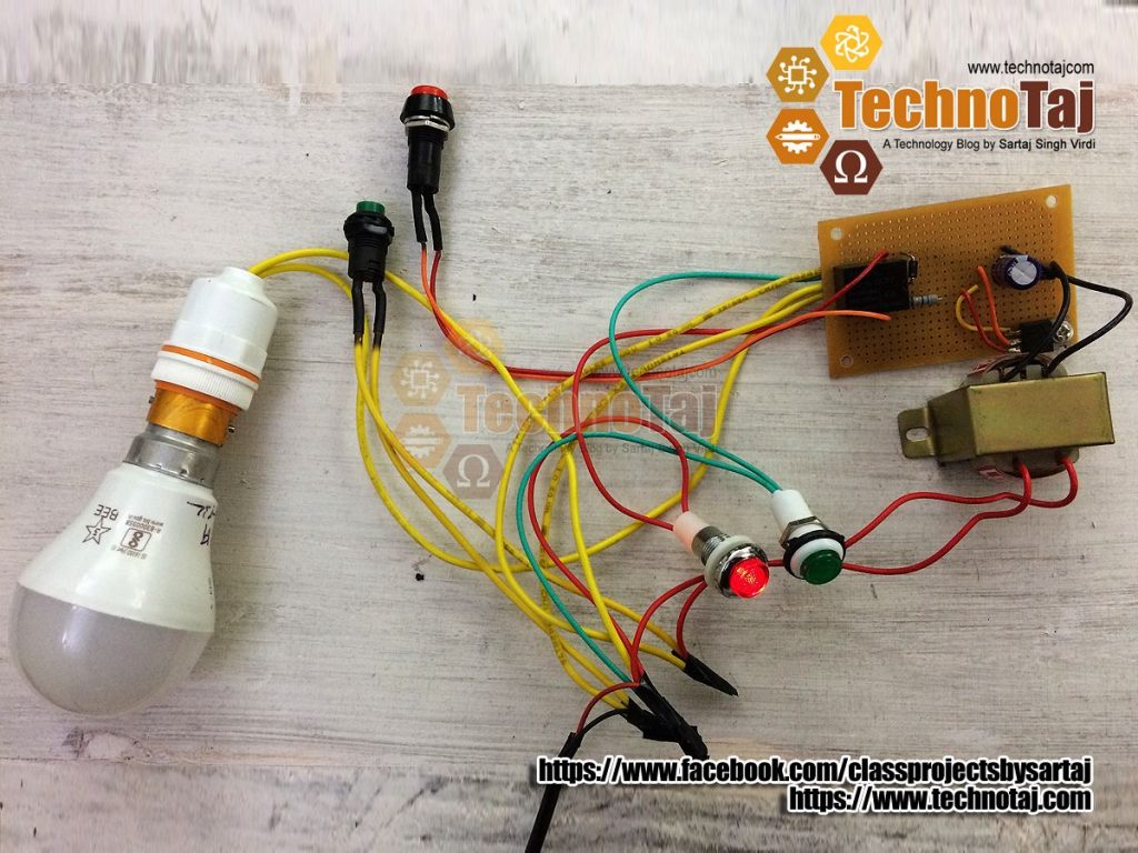
Just assemble the circuit as shown in the Circuit-01. Once you press the Green ‘Push-To-On’ Button it powers up the circuit and the relay is activated closing the N/O and making the circuit complete and it maintains its state to ON. Half wave rectification on the secondary coil of the transformer is good enough to power the relay adequately.
Now, if you press the Red ‘Push-To-On’ Button the power to the relay is bypassed through a 47Ohm 1-Watt shunt resistor, hence deactivating the relay, load and the circuit itself. It will maintain it’s OFF state until the Green ‘Push-To-On’ Button is pressed again.
Soft Latch Circuit - 02

Latch Switch Circuit Number 2
Just assemble the circuit as shown in the Circuit-02. Once you press the Green ‘Push-To-On’ Button it powers up the circuit and the relay is activated closing the N/O and making the circuit complete and it maintains its state to ON. Half wave rectification on the secondary coil of the transformer is good enough to power the relay adequately.
Now, if you press the Red ‘Push-To-Off’ Button the power to the entire circuit is cut, hence deactivating the relay, load and the circuit itself. It will maintain it’s OFF state until the Green ‘Push-To-On’ Button is pressed again.
Components Required
- Red Neon Indicator
- Green Neon Indicator
- 1 x 9V Relay
- Push to ON button x 1
- Push to OFF button x 1
- 1 x 9V (100mA) Transformer
- 1 x Fuse
- 1000uf 25V Capacitor
- 47Ohm 1Watt Resistor
- 2 x 1N4001 Diodes
PRICE: Rs. 30/-
-

- Making of Latch Switch

-
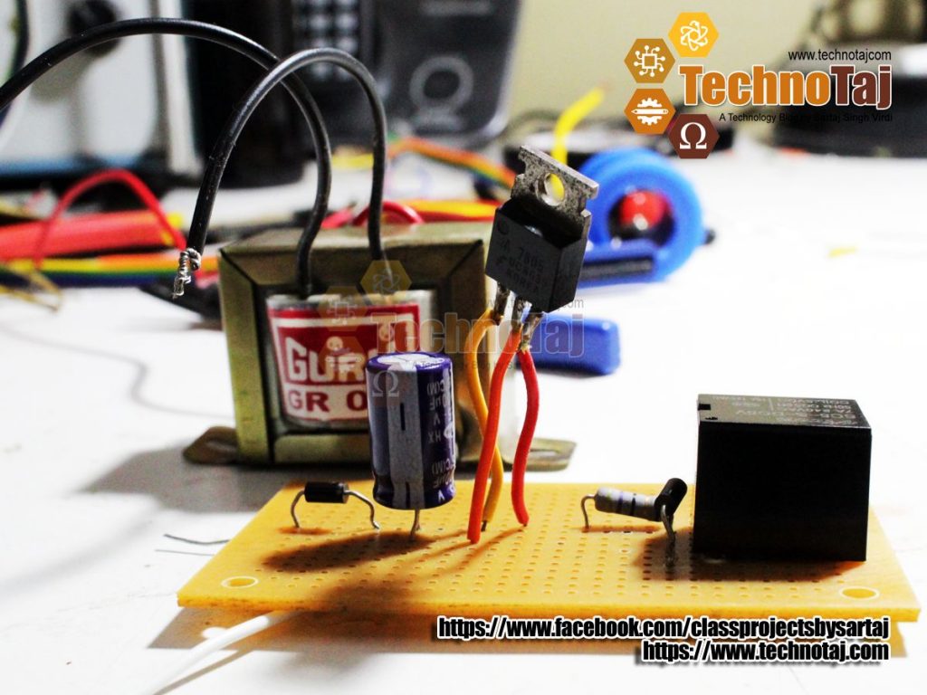
- Complete Latch Switch


-
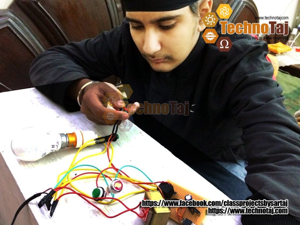
- Sartaj Singh Virdi Testing Latch Switch Circuit

-

- Latch Switch Close Up

-
- Latch Switch Complete

Demetrius Schmitz