Just clap and it will turn on or off the desired load. The USP of this circuit is that it is very sensitive. This circuit is very old, but I tried, built and repackaged it as a school project for one of my friend. He is happy with the results.
Circuit Description
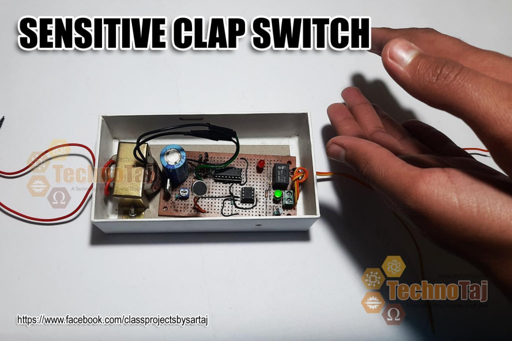
Here is a simple yet very sensitive clap switch project that works well in a 15x15 room size provided that you use shielded wire while connecting the condenser mic to the circuit. It will switch ON/OFF any electrical load with just a clap. The circuit derives a relay which in turn derives the load connected to the relay’s N/O points.

Clap Switch
The main component of this circuit is the Electric Condenser Microphone. This little microphone converts the sound of a clap into electrical energy which is inverted and fed to the most commonly used and our very-very old friend Operational Amplifier IC 741. It amplifies the sound collected from the condenser mic. Resistors and PCB Pot connected on Pin 3 of the IC741 are used to adjust the sensitivity of the clap switch. The values used by me in the circuit are optimum.
The amplified output pulses from the Operational Amplifier IC741 are passed into the input ‘pin 14’ of CD 4017 (CMOS decade counter). The IC CD4017 receives a clock signal through the clock input and it turns ON all the 10 outputs one by one, every time it gets the clock input pulse. When you clap once, the relay is activated and ‘LOAD’ is turned ON. When you clap for the second time, the relay is deactivated and the ‘LOAD’ connected to the relay is turned OFF.

Photoshoot of Clap Switch
Some advantages of the Clap Switch
- You can turn ON or OFF any electrical device or an appliance with a clap without moving from your place.
- You can also control speed of the fan or intensity of a bulb (not LED) by connecting a regulator with individual outputs of CD4017.
- There is no fear of any electrical shock as you are not required to physically touch any of the mechanical switches.
Disadvantages of this Clap Switch
- You create noise – and will be unacceptable if you clap when someone is sleeping near you.
- Also, there is continuous power drain even when the lights or loads are switched OFF through the circuit as it is kept ON forever.
Components Required
- 1 x CD 4017
- 1 x IC 741
- 1 x BC547 Transistor
- 1 x 10K Resistor
- 1 x 1K Resistor
- 3 x 470Ω Resistors
- 1 x 22K Resistor
- 1 x 100Ω Resistor
- 1 x 100uf 25V Capacitor
- 1 x 1000uf 25V Capacitor
- 1 x 7809 Regulator IC
- 1 x 9 Volt Relay
- 1 x Red LED
- 1 x Green LED
- 1 x General purpose bridge rectifier (or 4 x 1N4001)
- 1 x 0-9V (250mA) Transformer
- 1 x 1KΩ PCB Pot
- 1 x General Purpose PCB (Small)
- 1 x .5Amp Fuse
- 1 x Additional 1N4001
PRICE: Rs. 100/-
-

- Clap Switch Circuit

-
- Clap to ON

-
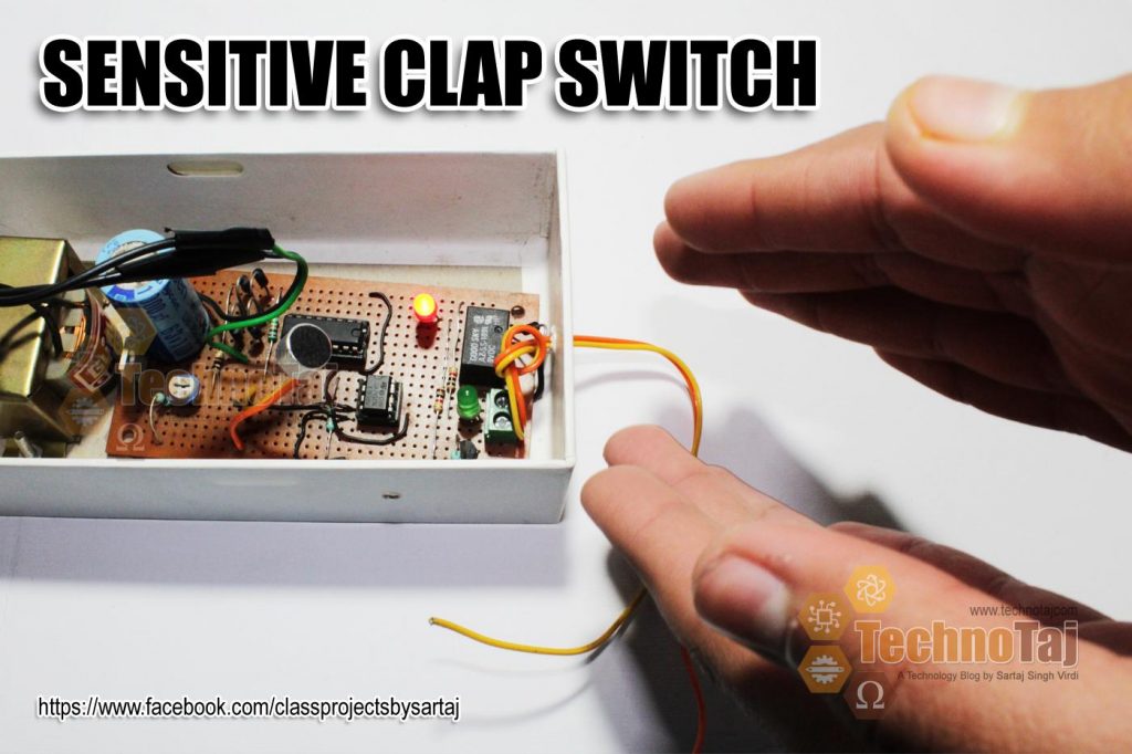
- Clap to OFF

-

- Mobile Box used as Clap Switch Cabinet

-
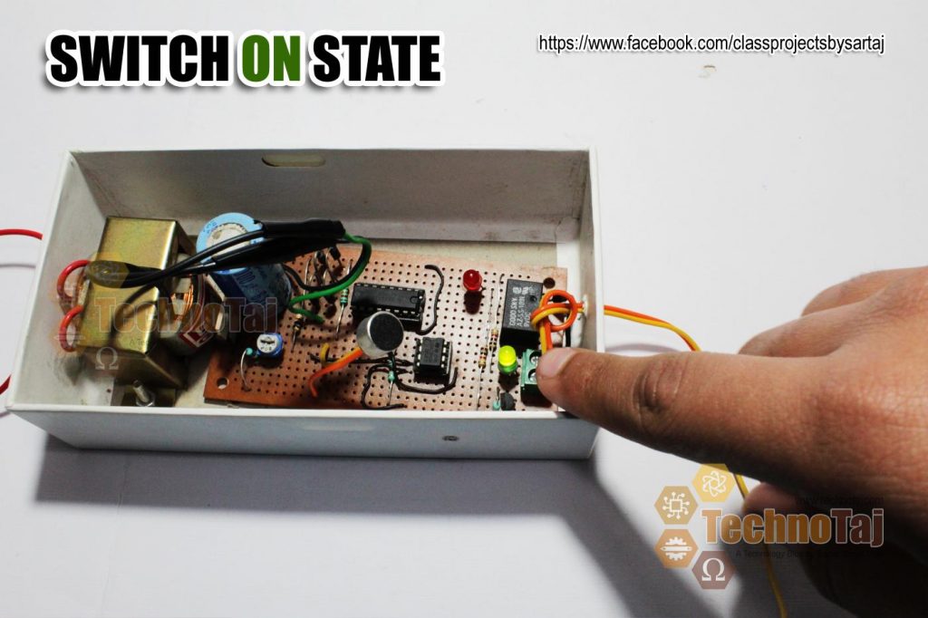
- Clap Switch ON State

-
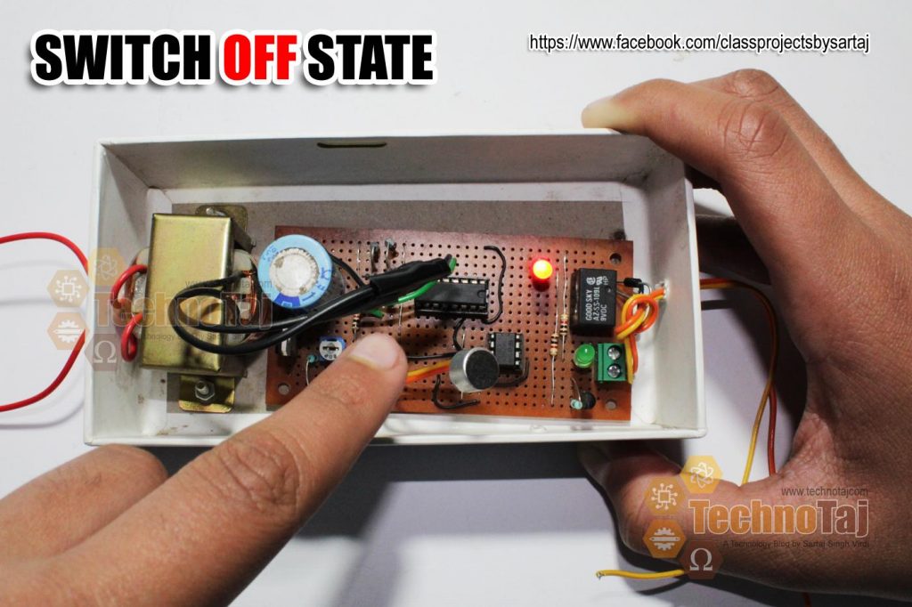
- Clap Switch OFF State

-

- Clap Switch PCB Solder

-
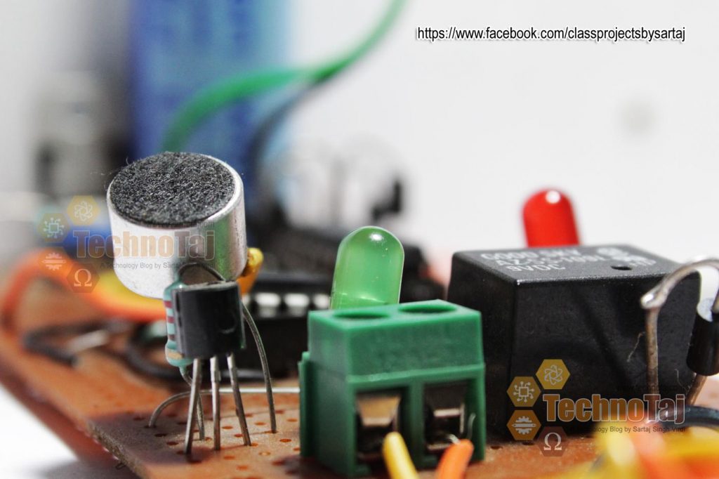
- Clap Switch Close Up

Anil
Sartaj Singh Virdi
Rohit
Sartaj Singh Virdi
Yugank Sharma
Sartaj Singh Virdi
khan muhammad
Sartaj Singh Virdi
Anil mehta
Sartaj Singh Virdi
Deepak
Sartaj Singh Virdi