Here is another project that I just completed. It is an old circuit wired around one of the most reliable monolithic IC LM3914. This IC can derive 10 LEDs based on analog input to its pin 5. The circuit can be calibrated with the 10K POT provided to test the actual power of a battery - it can easily test the power of 6Volts Battery, 9Volts Battery and 12Volts Battery in real-time.
Uses:
I have asked my father to keep it in the dashboard of his car for emergencies. I calibrated it for 12Volt battery. Now just plug it on to the battery of the car and try to switch on your car. If the indication graph rolls back to RED or YELLOW that means the battery needs replacement. If the indication graph stays within BLUE and GREEN - then the battery is in perfect shape. Load on a battery is measured in form of graph or dot based on a selection you make using SPST switch on the circuit.
About Project:
This Real-Time Actual Battery Indicator & Tester using LM3914 is a circuit that can be used as School Project for Kids. The heart of the circuit is our old and very friendly LM3194 IC that has been around for ages now. It is a chip which can drive 10 LEDs based on a linear input voltage value to its pin number 5. As the voltage on pin 5 increases the LEDs begin to glow one by one. This IC offers two modes of operation to display its output - Bar and Dot. That means you can select if you wish to see all the LEDs lit in a bar type graph or single LED lit as Dot type.

Real-time Actual Battery Indicator & Tester
The Circuit of Battery Indicator Using LM3914
The circuit diagram is self explanatory and very easy to make even if you are trying to make it for the first time. The LM3914 is a monolithic IC that are used as analog-controlled LED drivers. With LM3914, all it takes is a single, analog signal to drive a string of 10+ LEDs, which can be configured into either bar mode (where all LEDs below a certain point turn on) or dot mode (with only a single LED on at a time). Just connect it properly, and you can create many type of of nifty multi-LED displays - like Volume Unit Meter (VU meter) that shows the audio level indication - however for the purpose of this project I am configuring this circuit to display the voltage supplied to the input pin 5 as battery level indicator.
This electronic project for kids is an ideal school project for all levels of students.

Battery Level Indicator using LM3914 Circuit
Required Components
-
- LM3914 IC x 1
- Resistor 68KΩ x 1
- Resistor 4.7KΩ x 1
- Resistor 47KΩ x 1
- Red LEDs x 3
- Green LEDs x 3
- Yellow LEDs x 3
- Blue/White LED x 1
- PCB Mounting 10KΩ pot
- Few Cables
- General Purpose PCB
- SPST Micro Switch
- Regulated Power Supply to Calibrate the Circuit for the desired Battery
Other Material
-
- A Small Box (to install the circuit) - I used my mother's ear-ring box.
Cost of Project: INR 80/-
Facebook: https://www.facebook.com/classprojectsbysartaj/ | Instagram: https://www.instagram.com/classprojectsbysartaj/
-
- Real-time Actual Battery Indicator & Tester
-
- Battery Level Indicator using LM3914 Circuit
-

- Creating Holes for LEDs using Safety Pin & Candle
-

- Creating Holes for LEDs using Safety Pin & Candle
-
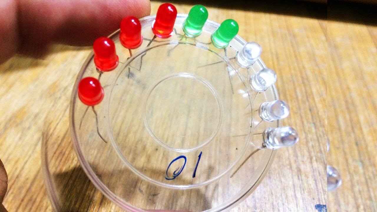
- Inserting LEDs to all the holes
-

- Inserting LEDs to all the holes
-

- Soldered all the anodes of LEDs together
-
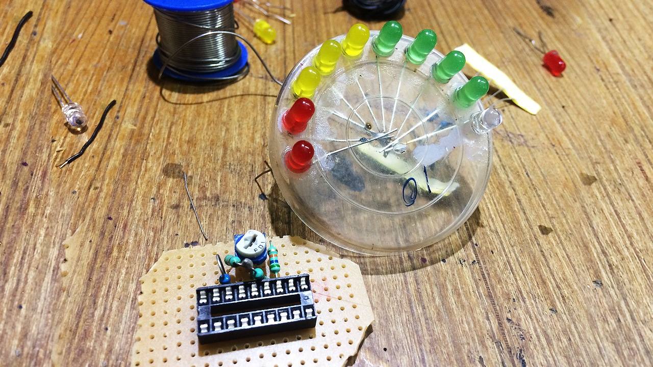
- Started to build the main circuit
-
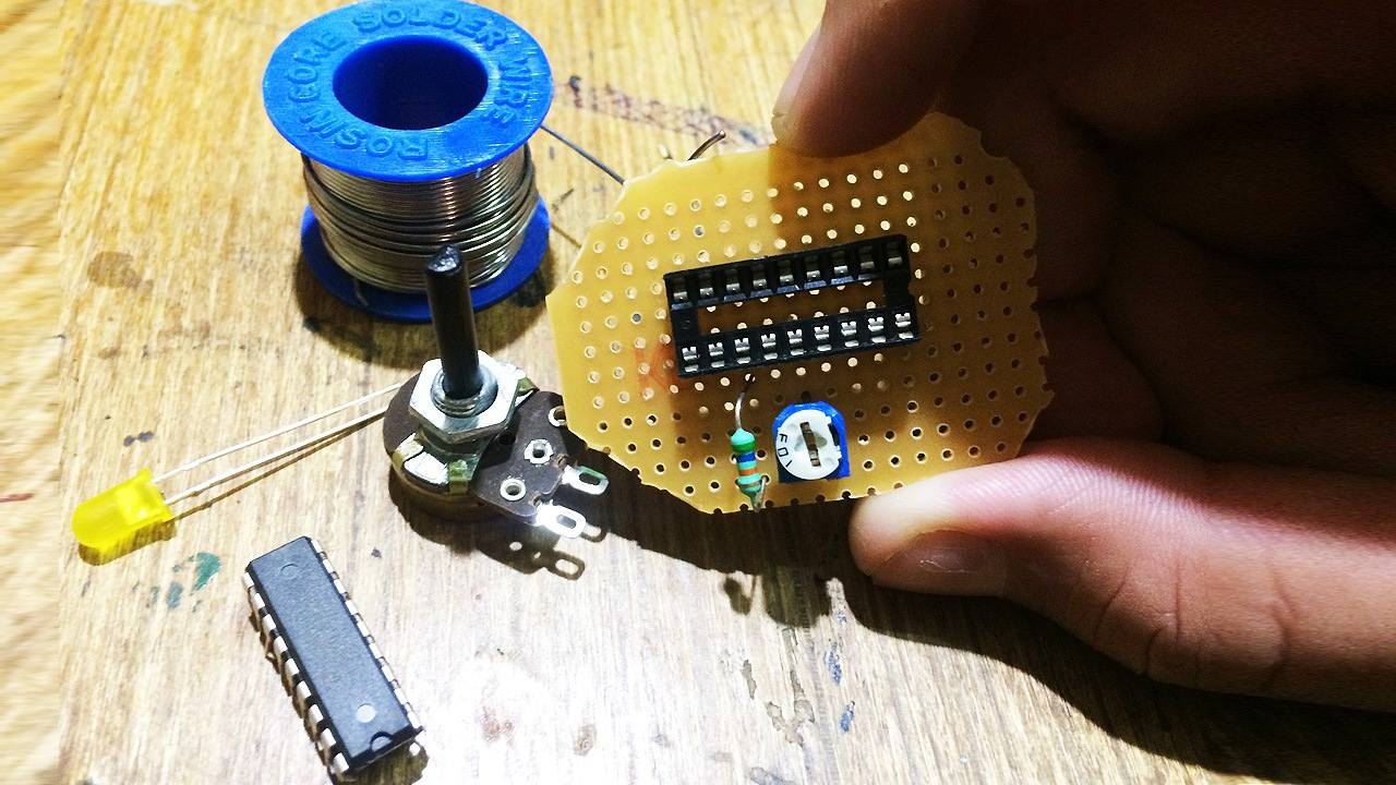
- Soldering the components on the general purpose PCB
-

- Finalizing all the component installation on the PCB
-

- Re-checking all the components
-
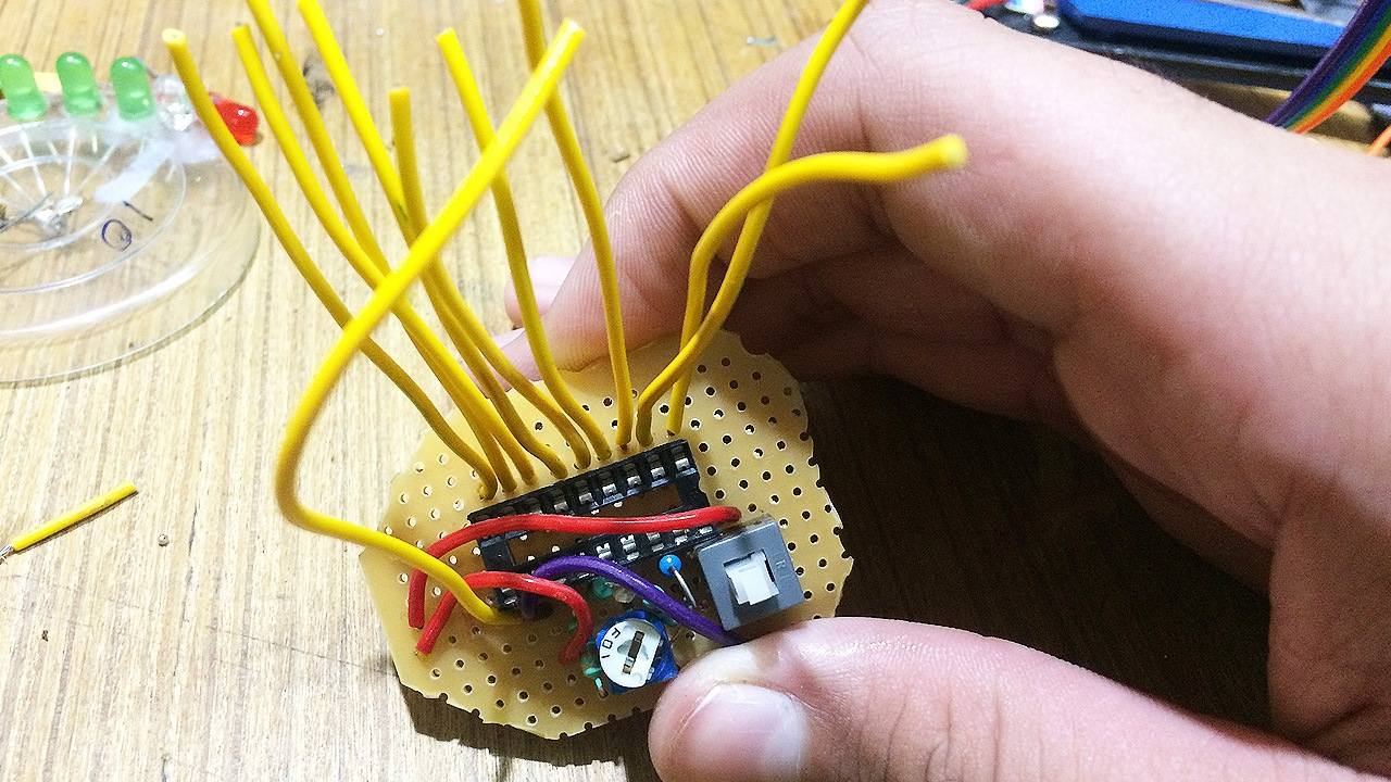
- Soldered all the wires for the LEDs
-
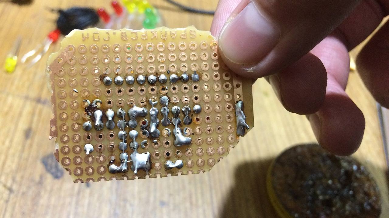
- Back-side of the soldered PCB
-
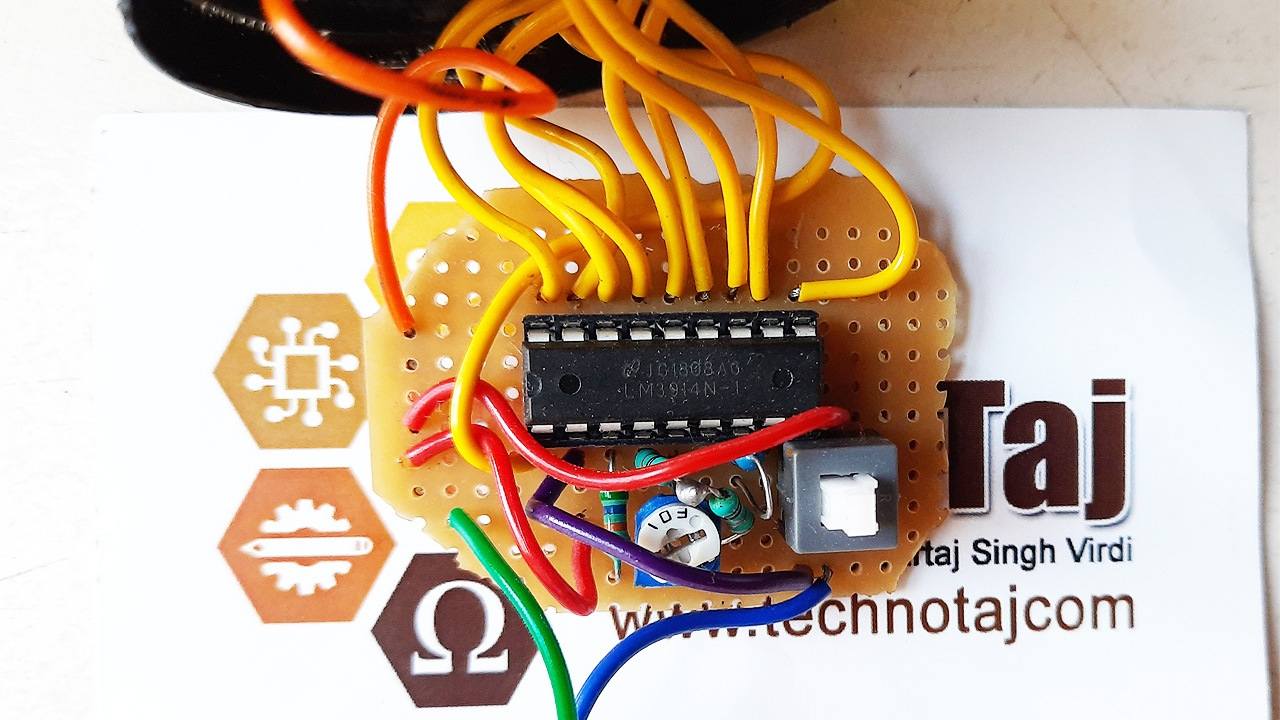
- That’s how the circuit Looks when complete
-

- Battery Level Indicator is now ready
-

- Final view of LM3914 based Voltage Indicator
Darvish
Sneha
rodblochon
Sartaj Singh Virdi